
Title: Determination of Viscosity
- Objective: To determine the Viscosity of liquids.
- Principle: The viscosity of a fluid is a measure of its resistance to gradual deformation by shear stress or tensile stress.The dynamic (shear) viscosity of a fluid expresses its resistance to shearing flows, where adjacent layers move parallel to each other with different speeds.
3. Procedure:
- Definitions:
- Shear thickening:Liquids whose viscosity increases with the rate of shear strain.
- Shear thinning:Liquids whose viscosity decreases with the rate of shear strain.
- Thixotropic:Liquids that become less viscous over time when shaken, agitated, or otherwise stressed.
- Rheopectic:Liquids that become more viscous over time when shaken, agitated, or otherwise stressed.
- Bingham plastics: Plastics that behave as a solid at low stresses but flow as a viscous fluid at high stresses.
- Method:
The determination of viscosity of newtonian liquids is carried out by means of a capillary viscometer, unless otherwise specified; Methods A and B described below are recommended. For non-newtonian liquids Method C using the rotating viscometer may be used.
For measurement of viscosity, the temperature of the substance being measured must be accurately controlled, since small temperature changes may lead to marked changes in viscosity. For usual pharmaceutical purposes, the temperature should be maintained to within ± 0.1°.
- Method A(Using Ostwald-type Viscometer)
Apparatus
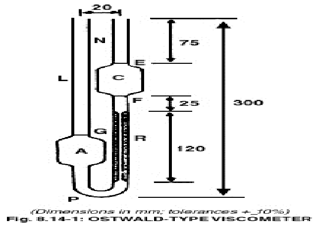
The apparatus consists of a glass U-tube viscometer (see Fig. 1) made of clear borosilicate glass and constructed in accordance with the dimensions shown in the figure and in Table 1. – U-Tube Viscometer – Dimensions.
Table 1 – U-Tube Viscometer – Dimensions
| Size | National viscometer constant | Kinematic Viscosityrange |
Inside diameter of tube |
Outside diameter of tubes* |
Volume of bulb |
Vertical
distance |
Outside diameter of bulbs |
|
| R | L | PN | C | F to G | A & C | |||
| m²s-² | mm²s-1 | mm (±2%) | mm | mm | ml (±5%) | mm | mm | |
| A** | 0.003 | 0.9 to 3 | 0.50 | 8 to 9 | 6 to 7 | 5. 0 | 91 ± 4 | 21 to 23 |
| B | 0.01 | 2.0 to 10 | 0.71 | 8 to 9 | 6 to 7 | 5.0 | 87± 4 | 21 to 23 |
| C | 0.03 | 6 to 30 | 0.88 | 8 to 9 | 6 to 7 | 5.0 | 83 ± 4 | 21 to 23 |
| D | 0.1 | 20 to 100 | 1.40 | 9 to 10 | 7 to 8 | 10.0 | 78 ± 4 | 25 to 27 |
| E | 0.3 | 60 to 300 | 2.00 | 9 to 10 | 7 to 8 | 10.0 | 73± 4 | 25 to 27 |
| F | 1.0 | 200 to 1000 | 2.50 | 9 to 10 | 7 to 8 | 10.0 | 70 ± 4 | 25 to 27 |
| G | 3.0 | 600 to 3000 | 4.00 | 10 to 11 | 9 to 10 | 20.0 | 60 ± 3 | 32 to 35 |
| H | 10.0 | 2000 to 10,000 | 6.10 | 10 to 11 | 9 to 10 | 20.0 | 50 ± 3 | 32 to 35 |
* Use 1 to 1.25 mm wall tubing for N.P and L
** 300 s minimum flow time; 200 s minimum flow time for all other sizes.
Procedure:
Fill the viscometer, previously washed and completely dried, with the liquid being examined through tube L to slightly above the mark G, using a long pipette to minimise wetting the tube above the mark. Place the tube vertically in a water-bath maintained at the temperature indicated in the monograph and allow to stand for not less than 30 minutes to allow the temperature to reach equilibrium. Adjust the volume of the liquid so that the bottom of the meniscus settles at the mark G. Suck or blow the liquid to a point about 5 mm above the mark E. After releasing pressure or suction, measure the time taken for the bottom of the meniscus to fall from the top edge of mark E to the top edge of mark F.
Calculate, as required, either the kinematic viscosity (v) in square millimeters per seconds (mm² s-1) from the expression: v = Kt
or the dynamic viscosity (n) in millipascal seconds (mPa s) from the expression
n = KPt,
where, t = time in seconds for the meniscus to fall from E to F,
P = mass/volume (g cm-3) obtained by multiplying the relative density, of the liquid
being examined by 0.998203.
The constant (K) of the instrument is determined on a liquid of known viscosity.
- Method B (Using the Suspended-level viscometer)
Apparatus
The apparatus consists of a glass suspended-level viscometer (see Fig. 8.14-2) made of clear borosilicates glass and constructed in accordance with the dimension shown in the figure and in Table 2.
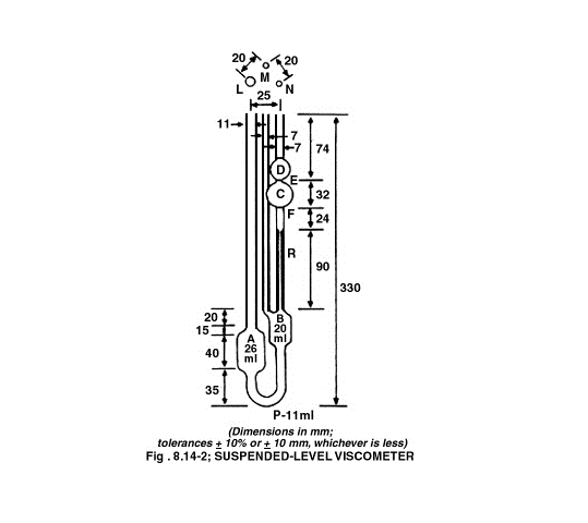
Table-2 Suspended –level viscometer—dimensions
| Size | National viscometer constant
m²s-² |
Kinemactic Viscosity rangemm²s-1 |
Inside diameter of tube Rmm (±2%) |
Volume of bulbCmm |
Inside diameter of tube N
mm |
| 1* | 0.01 | 3.5 to 10 | 0.64 | 5.6 | 2.8 to 3.2 |
| 1A | 0.03 | 6 to 30 | 0.84 | 5.6 | 2.8 to 3.2 |
| 2 | 0.1 | 20 to 100 | 1.15 | 5.6 | 2.8 to 3.2 |
| 2A | 0.3 | 60 to 300 | 1.51 | 5.6 | 2.8 to 3.2 |
| 3 | 1.0 | 200 to 1100 | 2.06 | 5.6 | 3.7 to 4.3 |
| 3A | 3.0 | 600 to 3000 | 2.74 | 5.6 | 4.6 to 5.4 |
| 4 | 10.0 | 2000 to 10,000 | 3.70 | 5.6 | 4.6 to 5.4 |
| 4A | 30.0 | 6000 to 30,000 | 4.97 | 5.6 | 5.6 to 6.4 |
| 5 | 100.0 | 20,000 to 100,000 | 6.76 | 5.6 | 6.8 to 7.5 |
* 350 s minimum flow times; 200 s minimum flow time for all other sizes.
Procedure:
Fill the viscometer through tube L with a sufficient quantity of the liquid being examined to ensure that bulb A is satisfactorily filled without blocking the ventilation tube M. After the tube has been placed vertically in a bath maintained at the specified temperature allow it to stand for not less than 30 minutes to allow the temperature to reach equilibrium, close tube M and apply suction to tube N until the liquid reaches a level about 5 mm above mark E. Hold the liquid at this level by closing tube N and open tube M. when the liquid is clear of the capillary end of tube N and the lower end of tube M, open tube N. Measure the time taken, to the nearest 0.2 of a second, for the bottom of the meniscus to fall from the top edge of mark E to the top edge of mark F.
If the end of tube M becomes blocked by the liquid at any time while the flow time is being measured, the determination must be repeated.
The result is not valid unless two consecutive readings do not differ by more than 1%. The average of not fewer than three readings gives the flow time of the liquid being examined.
Calculate the kinematic viscosity (v) or the dynamic viscosity (h) as given under Method A.
- Method C: (Using the rotating Viscometer)
The rotating viscometer measures the shearing forces in a liquid medium placed between two coaxial cylinders one of which is driven by a motor and the other is caused to revolve by the rotation of the first. Under these conditions, the viscosity becomes a measurement of the angle of deflection of the cylinder caused to revolve, expressed in newton metres.
The principle of the method is to measure the force acting on a rotor (torque) when it rotates at a constant angular velocity (rotational speed) in a liquid. Rotating viscometers are used for measuring the viscosity of Newtonian (shear-independent velocity) or non-Newtonian liquids (shear dependent viscosity or apparent viscosity). Rotating viscometers can be divided into 2 groups, namely absolute and relative viscometers. In absolute viscometers the flow in the measuring geometry is well defined. The measurements result in absolute viscosity values, which can be compared with any other absolute values. The relative viscometers, the flow in the measuring geometry is not defined. The measurements results in relative viscosity values, which cannot be compared with absolute values or other relative values if not determined by the same relative viscometer method.
Different measuring systems are available for given viscosity range as well as several rotational speeds.
Procedure:
Operate the Rotating Viscometer in accordance with the manufacturer’s instruction and carry out the determination of viscosity of the liquid being examined, at the temperature and angular velocity or shear rate specified in the individual monograph.
If it is not possible to obtain the indicated shear rate exactly, use shear rates slightly higher and slightly lower than the indicated value and interpolate.
Calculate the dynamic viscosity (h) is pascal seconds (Pa s) from the expression
h =KL/w,
where L = the angular momentum in newton meters,
w = the angular speed in radians per second.
The constant (K) of the instrument is determined using a liquid of known viscosity or by reference too tables supplied by the instrument manufacturer.